简介
本文主要是针对新思的I2C控制器的学习的第二篇文章
本文涉及:
Uboot下I2C控制器驱动实现分析
OPS
1 | static const struct dm_i2c_ops designware_i2c_ops = { |
I2C驱动回调接口
designware_i2c_xfer
根据msg里的flags来决定具体执行read还是write接口
1 | static int designware_i2c_xfer(struct udevice *bus, struct i2c_msg *msg, |
1 | /* |
read接口导读:
1 | static int __dw_i2c_read(struct i2c_regs *i2c_base, u8 dev, uint addr, |
designware_i2c_probe_chip
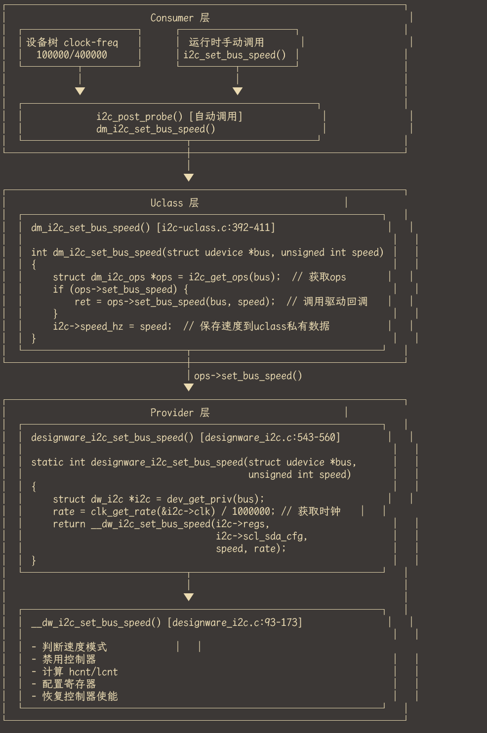
designware_i2c_set_bus_speed
整体架构:
超时机制
超时处理机制详解
该驱动中有多个关键的超时检查点,防止在异常情况下系统死锁。
- 控制器使能/禁用超时 (第64-84行)
1 | static int dw_i2c_enable(struct i2c_regs *i2c_base, bool enable) |
目的:使能/禁用控制器时,硬件可能需要时间响应,通过轮询 ic_enable_status 寄存器确认状态变化。
机制:
- 最多重试 100 次
- 每次间隔 25µs(400KHz I2C 信号周期的 10 倍)
- 总超时时间约 2.5ms
- 等待总线空闲超时 (第208-221行)
1 | static int i2c_wait_for_bb(struct i2c_regs *i2c_base) |
目的:等待总线从忙碌状态变为空闲。
检查条件:
- IC_STATUS_MA:总线是否被占用
- IC_STATUS_TFE:TX FIFO 是否为空
超时时间:I2C_BYTE_TO_BB(通常定义为毫秒级)
- 等待停止条件超时 (第239-260行)
1 | static int i2c_xfer_finish(struct i2c_regs *i2c_base) |
目的:等待 I2C 停止条件检测完成。
机制:
- 轮询 ic_raw_intr_stat 的 IC_STOP_DET 位
- 超时后跳出循环继续执行(不会无限等待)
- 再检查总线是否空闲
- 读操作字节超时 (第300-325行)
1 | start_time_rx = get_timer(0); |
目的:读取每个字节时防止从机无响应。
机制:
- 每成功读取一个字节,重置计时器
- 若在 I2C_BYTE_TO 时间内未收到数据,返回错误
- 写操作字节超时 (第368-384行)
start_time_tx = get_timer(0);
while (len) {
if (readl(&i2c_base->ic_status) & IC_STATUS_TFNF) {
if (–len == 0) {
writel(*buffer | IC_STOP, &i2c_base->ic_cmd_data);
} else {
writel(*buffer, &i2c_base->ic_cmd_data);
}
buffer++;
start_time_tx = get_timer(0); // 重置计时器
  } else if (get_timer(start_time_tx) > (nb * I2C_BYTE_TO)) {
      printf("Timed out. i2c write Failed\n");
      return 1;
  }
}
目的:写入数据时等待 TX FIFO 有空间。
特点:超时时间与写入字节数 nb 成正比,写越多数据等待越久。
超时处理总结图
┌─────────────────────────────────────────────────────────────┐
│ I2C 传输流程 │
├─────────────────────────────────────────────────────────────┤
│ │
│ dw_i2c_enable() ────► [使能超时 2.5ms] │
│ │ │
│ ▼ │
│ i2c_wait_for_bb() ──► [总线空闲超时 I2C_BYTE_TO_BB] │
│ │ │
│ ▼ │
│ i2c_xfer_init() ─────► 设置从机地址 │
│ │ │
│ ▼ │
│ ┌─────读/写循环─────┐ │
│ │ │ │
│ │ 每字节超时检查 │◄── [I2C_BYTE_TO 或 nb*I2C_BYTE_TO] │
│ │ │ │
│ └───────────────────┘ │
│ │ │
│ ▼ │
│ i2c_xfer_finish() ──► [停止条件超时 I2C_STOPDET_TO] │
│ │ [总线空闲超时] │
│ ▼ │
│ i2c_flush_rxfifo() ─► 清空 FIFO │
│ │
└─────────────────────────────────────────────────────────────┘
为什么需要这些超时?
┌────────────────┬──────────────────────────────────┬──────────────────┐
│ 场景 │ 可能原因 │ 无超时后果 │
├────────────────┼──────────────────────────────────┼──────────────────┤
│ 控制器使能失败 │ 硬件故障、时钟未使能 │ 系统卡死 │
├────────────────┼──────────────────────────────────┼──────────────────┤
│ 总线一直忙碌 │ 从机拉低 SCL/SDA、其他主设备占用 │ 无限等待 │
├────────────────┼──────────────────────────────────┼──────────────────┤
│ 读字节超时 │ 从机无响应、总线断开 │ 死循环 │
├────────────────┼──────────────────────────────────┼──────────────────┤
│ 停止条件未检测 │ 总线错误、仲裁丢失 │ 无法开始下次传输 │
└────────────────┴──────────────────────────────────┴──────────────────┘
这种多层超时设计确保了任何异常情况都不会导致系统完全卡死,而是返回错误码让上层决定如何处理(如重试、报错、复位控制器等)。